| Wire Grade | Diameter range (mm) | Chemical Compositions | |||||||
|---|---|---|---|---|---|---|---|---|---|
| C | Si | Mn | P | S | Cr | V | Co | ||
| SWOSC-V | 0.8-8.0 | 0.51-0.59 | 1.20-1.60 | 0.50-0.80 | -0.025 | -0.025 | 0.50-0.80 | - | - |
| SWOSC-VH | 2.0-6.5 | 0.63-0.68 | 1.30-1.60 | 0.60-0.80 | -0.025 | -0.025 | 0.50-0.80 | - | - |
| SWOSC-VHV | 2.0-6.5 | 0.63-0.68 | 1.20-1.60 | 0.50-0.80 | -0.025 | -0.025 | 0.50-0.80 | 0.10-0.20 | - |
| SWOSC-VHS | 2.0-6.5 | 0.63-0.68 | 1.80-2.20 | 0.70-0.90 | -0.025 | -0.025 | 0.50-0.80 | 0.05-0.15 | - |
| SWOSC-VHR | 2.0-5.0 | 0.63-0.68 | 2.10-2.30 | 0.50-0.70 | -0.025 | -0.025 | 1.10-1.30 | 0.10-0.20 | 0.10-0.30 |
Mechanical Properties
| Nominal Dia 1) (mm) | Tensile Strength (N/mm²) | Tolerance (mm) | Ovality (mm) | ||||
|---|---|---|---|---|---|---|---|
| SWOSC-V | SWOSC-VH | SWOSC-VHV | SWOSC-VHS | SWOSC-VHR | |||
| 2.0 | 1910-2060 | 2110-2210 | 2110-2210 | 2160-2260 | 2210-2310 | ±0.02 | 0.02 |
| 3.0 | 1860-2010 | 2060-2160 | 2060-2160 | 2110-2210 | 2160-2260 | ±0.02 | 0.02 |
| 4.0 | 1810-1960 | 2010-2110 | 2010-2110 | 2060-2160 | 2110-2210 | ±0.03 | 0.03 |
| 5.0 | 1760-1910 | 1960-2060 | 1960-2060 | 2010-2110 | 2060-2160 | ±0.03 | 0.03 |
Double Eddy Current Test
For 2.1~6.0mm in diameter, double eddy current tests, i.e. stationary and rotating types, are applicable.
| Wire Diameter(mm) | Coil Size(mm) | Coil Weight(kg) | ||
|---|---|---|---|---|
| Inner Diameter | Outer Diameter | Lapped Coil | Coil with Carrier | |
| 0.8-1.2 | 300 | 580 | 50 | 100 |
| 1.3-1.9 | 650 | 1100 | 100/200 | 400 |
| 2.0-2.9 | 650 | 1100 | 100/200 | 400 |
| 1000 | 1500 | 200/400 | 800 | |
| 3.0-5.5 | 1000 | 1500 | 200/400 | 800 |
| 5.6-8.0 | 1300 | 1500 | 200/400 | 800 |
(1)Manufacturing Process

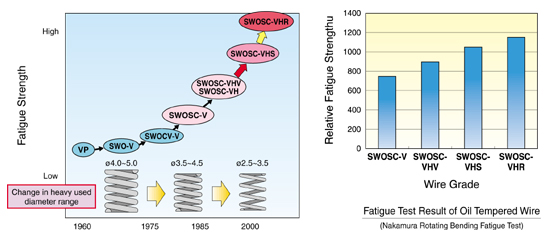
(2)Fatigue Strength

(3)Microscopic Test of Non-Metallic Inclusions (Max.T Method)
The samples are taken in wire rod state and those longitudinal sections are polished. For each sample, both the top and bottom surface zones that are from the surface to 2mm inside and having 15mm length shall be inspected (i.e. 60mm² area, see fig.1). For each heat, 10 samples shall be inspected and maximum thickness of observed non- metallic inclusions (see fig.2) shall not be 15μm or larger.


